STEP HEATING METHOD FOR THERMAL DIFFUSIVITY MEASUREMENT
Libor Vozár* and Tatiana Šrámková†
*Department of Physics, Constantine the Philosopher University,
Nitra, Slovakia
†Institute of Physics, Slovak Academy of Sciences, Bratislava,
Slovakia
Abstract: The paper presents the principle and mathematical basis
of the step heating method for thermal diffusivity measurement. Here the
known data reduction methods - procedures for analyzing the experimental
temperature vs. time data, are summarized. The simple experimental apparatus
is described and experimental results are given. The modification of the
step heating method - the radial heat flow step heating technique, suitable
for simultaneous measurement the axial thermal diffusivity (perpendicular
to the plane faces of the sample) and radial thermal diffusivity (parallel
to the plane faces), is described and discussed.
Keywords: thermal, diffusivity, step heating method
1 INTRODUCTION
The step heating method is an experimentally simple transient photothermal
technique for the measurement of thermal diffusivity of solids. In this
method the front face of a small thermally insulated disk-shaped sample
is subjected to a constant heat flux condition. The resulting temperature
rise of the rear face of the sample is recorded and the value of thermal
diffusivity is computed from this temperature rise vs. time data [1-3].
The step heating method is an alternative technique to the well-known
laser flash method, based on measurement and analyzing the temperature
response at the rear face after the application of an instantaneous heat
pulse on its front face [4]. Although the flash method has became the standard
test technique, extensions of its use for some types of insulators, explosive
and translucent materials is limited due to the relatively large temperature
rise of the exposed front face. There are also difficulties involved in
measuring the thermal diffusivity of large-grained heterogeneous materials,
especially oriented fiber-reinforced composites, where the scale of microstructure
is usually comparable with the used sample thickness. Substituting step
heating for laser pulse tends to overcome these difficulties. The possibility
to use samples of relatively large dimensions in comparison to those used
in the flash method allows to extend cases, where the material can be considered
to behave as a homogeneous medium. Another advantage of the step heating
method is relatively low intensity of the imposed heat flux in comparison
with that necessary for the pulse heating techniques. The sample is thereby
less likely to exhibit a phase transition or decompose as a result of a
sudden large temperature increase at the front face.
2 MATHEMATICAL BASIS
The ideal model of the step heating method is based on the behavior of
a homogeneous, thermally insulated, infinite slab, with uniform and constant
thermal properties and density, initially at constant (zero) temperature,
subjected to a constant heat flux, uniformly applied since the time origin
(t=0), over its front face (x=0). The transient temperature
T(x,t)=T(e,t) of the rear face of the sample
can be received in the form [1-3]
 . .
|
(1) |
Here a is the thermal diffusivity, r
the density, c the specific heat and q is the heat flux supplied
to the unit area of the front face. Use of the simple adiabatic model is
limited due to the difficulty of creating the ideal conditions considered
as initial and boundary conditions in the mathematical model. In a real
experiment heat transfer between the sample and its environment is often
unavoidable, especially at high temperatures and/or by measurement of poor
conductive materials.
The non-ideal model considers a disk-shaped sample with radius rs
and takes into account linearized heat losses from the sample governed
by Biot numbers related to front, rear and lateral faces (H0,
He and Hr ) [3]. The temperature T(x,r,t)=T(e,0,t)
in the center of rear face can be written as
 , ,
|
(2) |
where An, Bm, un,
and wm are variables defined in appendix.
3 DATA REDUCTION
An estimation of thermal diffusivity can be performed by comparing the
experimental data and temperature rise vs. time curves computed from an
appropriated model. This is possible by calculation and comparing of ratio
V of temperatures V=T(t1)/T(t2)
in various times t1 and t2 as proposed
in [1,2].
More efficient are parameter estimation techniques, based on a least
squares fitting. Conditions for successful application of a least-squares
fitting in data analysis result from sensitivity analysis, performed by
calculating normalized sensitivity coefficients, defined as
 . .
|
(3) |
Here b is the appropriated fit parameter and
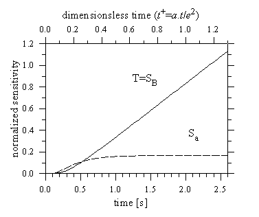
T is the temperature. When taking the ideal adiabatic model (1),
results show that sensitivity for thermal diffusivity a and sensitivity
for heat flux term B=q/rce
vs. time curves are linearly independent (figure 1). That means that the
necessary condition for least squares fitting is fulfilled and an unique
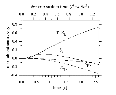
estimation of parameters a and B is possible [5]. Figure
2 shows results of sensitivity analysis performed considering the model
with heat losses from the axial (front, rear) and lateral faces (Ha=H0=He).
We see, that sensitivities for axial and radial Biot numbers are close
to being linearly dependent. This indicates, that the simultaneous estimation
of parameters Ha and Hr may be difficult,
therefore it is suitable to assume that there are equal axial and radial
heat transfer coefficients and axial and radial Biot numbers fulfill the
condition
 . .
|
(4) |
 Figure 1. Sensitivity coefficient curves for the
adiabatic model (1) (a=5.10-5 m2.s-1;
B=1 K.s-1; e=10 mm).
 Figure 2. Sensitivity coefficient curves for the
model with heat losses (2) (a=5.10-5 m2.s-1;
B=1 K.s-1; H0=He=0,1;
Hr=0,05; e=10 mm; rs=5 mm).
Thus data reduction consists of searching of three unknown parameters
a, B and Ha which unique estimation is possible.
The paper [3] detailed describes application of the ordinary least squares
(OLS) and the Levenberg-Marquardt (LM) fitting methods in the data reduction
process.
Another way is to utilize the Fourier transformation for transformation
of the experimental data and then to fit the image temperature with a proper
formula [6]. The main advantage of the method is in insensitivity of the
thermal diffusivity calculation on the temperature level before the step
heating application (base line) and in independency of results on the disturbing
of the data by a linearly rising or falling signal.
4 EXPERIMENTAL APPARATUS
The step heating apparatus built in the Thermophysical Laboratory in Nitra
consists of the heat source, a halogen lamp (12V/100W) with a parabolic
reflector, and the electrically controlled mechanical light shutter. The
lamp is powered by a direct current produced by stabilized current/voltage
supply Z-YE-2T-X (Mesit) with the unit of remote control JDR-1 (Mesit).
The setting of optimal current depends on sample thermal properties and
dimensions and is chosen so the rear face temperature rise reaches about
1-3°C in the measurement. The measurement time is taken from optimal
experimental design analysis (tn+=a.tn/e2
~ 5 when taking equation (2)[7]). The temperature rise at the rear face
is measured by spot welded K-type thermocouple (NiCr/Ni wires (Heraeus)
0,1 mm in diameter). The reference cold junction is immersed in Dewar cup
at 0°C. The transient emf of the thermocouple is amplified and digitized
by standard 12-bit A/D converter. The apparatus is fully controlled by
a PC.
For this apparatus a software package was written, which allows device
control, data acquisition and data analysis. The measurement cycle starts
with continuous measurement of rear face temperature vs. time evolution.
When a thermal equilibrium in the sample fixes, the data acquisition task
performs the data acquisition. When executed, it first switches on the
halogen lamp, and then the routine reads the transient voltage from the
temperature sensor. When the heat flowing from the lamp is stabilized and
after the time equal to 10% of the total measurement time the light shutter
puts on and the step (continuous) heating starts. The data acquisition
rate is controlled with the use of a quartz time base and 8253 counter.
The data reduction consists in performing least squares fits of the measured
temperature vs. time data as described in part 3. Then the data are analyzed,
the received results are printed and/or saved, and the described measurement
cycle starts again. That allows the measurement to be conducted in a fully
automatic way.
In order to demonstrate that the instrument operates in accordance with
the appropriated mathematical model, a number of measurement are performed.
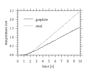
Figure 3 presents typical
 Figure 3. Experimental rear face temperature vs.
time curves (graphite e=27 mm; steel e=6 mm).
rear face temperature rise vs. time vs. time evolution obtained measuring
graphite and stainless steel samples at room temperatures. The received
values of thermal diffusivity gained using the OLS and LM together with
the values given by NIST [8,9] are given in the table 1.
Table 1. Thermal diffusivity of graphite and stainless steel
calculated using OLS and LM fitting method compared with recommended literature
values.

5 RADIAL HEAT FLOW STEP HEATING METHOD
Although the step heating method was originally designed for the measurement
of the thermal diffusivity of isotropic solids, the possibility of its
use for measurement of anisotropic material has been shown [10]. The radial
heat flow step heating method consists in irradiating the central circular
area of radius smaller than the sample radius. If the temperature response
is measured at rear face the axial thermal diffusivity (perpendicular to
the plane faces of the sample) as well as radial thermal diffusivity (parallel
to the plane faces) can be deduced from these temperature rise vs. time
curves.
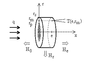
Let us consider a cylindrical sample of radius rs
and thickness e subjected to a constant heat flux per unit surface
q, uniformly applied since the time origin over a central circular
area of radius rp smaller than sample radius rs
(figure 4). This presents a symmetry around the principal
 Figure 4. Mathematical model of the radial heat flow
step heating method.
axis x and it is easy to show, that the transient temperature T=T(x,r,t)
in position (x,r) of the sample can be expressed by formula
 , ,
|
(5) |
where aa is the axial and ar the radial
thermal diffusivity. It was shown, that the temperature evolution measured
at rear face may contain enough information for a unique estimation of
both diffusivities [10].
The measurement of a temperature rise response curves in several different
positions on rear face increases the precision of the radial thermal diffusivity
estimation, which is in general strongly dependent on the knowledge of
exact detector position, difficult to measure precisely. The use of repeated
measurements results not only in decreasing statistical errors, but also
in minimizing the influence of many experimental errors, like calibration
errors of temperature sensors, local sample material non-homogenities,
uncertainties in knowing temperature sensor locations, etc.
Sensitivity analysis shows that the data reduction - estimation parameters
aa, ar, B and H, based
on a least squares fitting can be succesfully applied for unique estimation
of all parameters. The data reduction can be viewed as an explicit multiresponse
ordinary least squares problem for multivariate explanatory data. Results
of Monte Carlo simulations and simulated data analysis confirm, that both
- axial and radial thermal diffusivity can be estimated with the similar
accuracy [10].
APPENDIX
 , H0
> 0; He > 0

 , Hr
> 0
where un and wm are the positive
roots of equations

 ,
,
and J0 and J1 are Bessel functions of the first
kind, order 0 and 1.
REFERENCES
[1] R.R. Bittle, R.E. Taylor, Step-heating technique for
thermal diffusivity measurements of large-grained heterogeneous materials,
J. Amer. Ceram. Soc. 67 (1984) 186-190.
[2] R.R. Bittle, R.E. Taylor, Thermal diffusivity of
heterogeneous materials and non-fibrous insulators, in T. Ashword , D.R.
Smith (ed.), Thermal Conductivity, Vol. 18, Plenum, New York, 1985,
p. 379-390.
[3] L. Vozár, T. Šrámková, Two data
reduction methods for evaluation of thermal diffusivity from step heating
measurements, Int. J. Heat Mass Transfer (in press)
[4] W.J. Parker, R.J. Jenkins, C.P. Butler, G.L. Abbott,
Flash method of determining thermal diffusivity, heat capacity and thermal
conductivity, J. Appl. Phys. 32 (1961) 1679-1684.
[5] J.V. Beck, K.J. Arnold, Parameter Estimation in
Engineering and Science, John Wiley and Sons, New York, 1977, 349 p.
[6] J. Gembaroviè, R.E. Taylor, Using the cosine
Fourier transform in thermal diffusivity measurement, High Temp. High
Press (accepted).
[7] L. Vozár, G. Groboth, Thermal diffusivity
measurement of poor conductive materials. A comparison of step heating
to flash method, High Temp. High Press (accepted).
[8] J.G. Hust, A.B. Lankford, A fine-grained, isotropic
graphite for use as NBS thermophysical property RM's from 5 to 2500 K.
National Bureau of Standards, 1984, p. 260-289.
[9] J.G. Hust, A.B. Lankford, Austenitic stainless steel
thermal conductivity and electrical resistivity as a function of temperature
from 5 to 2500 K. National Bureau of Standards, Certificate Standard Reference
Materials 1460, 1461, 1462, Washington DC, 1984.
[10] L. Vozár, T. Šrámková, Simultaneous
measurement of axial and radial thermal diffusivities of anisotropic media
using the radial heat flow step heating method, High Temp. High Press.
(accepted).
Contact point: Libor Vozár, Department of Physics,
Faculty of Natural Sciences, Constantine the Philosopher University, Tr.
A. Hlinku 1, SK-94974 Nitra, Slovakia, Phone + 42 87 511073, Fax + 42 87
511243, E-mail: lvozar@ukf.sk
 .
. .
. ,
,


 ,
, , H0
> 0; He > 0
 , Hr
> 0