Flash Method for the Thermal Diffusivity Measurement
3. Sample sizes
4. References
1. Description of the method
The laser flash method, proposed by Parker, Butler, Jenkins, and Abbott of the U.S. Navy Radiological Defense Laboratory in 1960 [1], is the most popular method of measuring the thermal diffusivity of solids. In this method the front face of a small plane sample (usually disk-shaped) thermally insulated sample is subjected to a very short burst of radiant energy coming from a laser or a xenon flash lamp. The resulting temperature rise on the opposite (rear) face of the sample is measured, and the thermal diffusivity is computed from the temperature rise vs. time data. The rear face temperature rise reaches usually 1 to 3ºC and its time evolution has typically the form as shown in the figure.
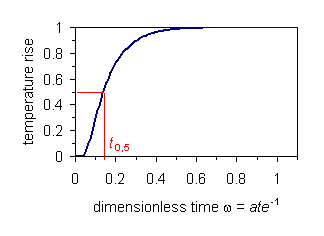
The classical way to calculate the thermal diffusivity from the experimental data is based on the knowledge of a characteristic point of temperature vs. time data – the half time (t0,5), i. e., the time which corresponds to a rise in the temperature to half of its maximum value (Tmax). The working equation is
|
|
(1) |
where e is the thickness of the sample. Several other data reduction methods (algorithm for computing the thermal diffusivity from experimental data) have appeared so far. They differ either on the analytical model used or by the way of comparing the measured experimental temperature rise vs. time recordings and the analytical curve [2].
More about the current state-of-the-art concerning thermal diffusivity measurements using the flash method can be find in [3,4].
2. Experimental apparatus
The home-made experimental apparatus was developed especially for measurements of the thermal diffusivity of poor thermal conductive materials. Here either xenon flash lamp or halogen lamp acts as the heat-pulse source. The temperature and the temperature rise vs. time evolution is measured by thermocouples. The sample is heated by electro resistive furnace. All data acquisition and temperature control is computer-controlled. Calculation of the thermal diffusivity is performed by most of the known data reduction and correction methods. It is possible to take into account the ideal adiabatic boundary conditions, as well as those non-ideal that consider heat transfer between all sample surfaces and its environment, consider finite pulse time effects, etc [2]. The apparatus allows to study two- and three-layered materials as well as to study anisotropy of the measured material.
The apparatus currently allows performing in-situ measurements of solid materials in the temperature range 20 – 800 ºC.
3. Sample sizes
The samples have the shape of the disk with 10 mm in diameter, thickness varies in range 1-5 mm depending on the thermal diffusivity of the measured material.
4. References
|
[1] |
Parker W J, Jenkins W J, Butler C P, Abbott G L, Flash Method of Determining Thermal Diffusivity, Heat Capacity and Thermal Conductivity, 1961, J. Appl. Phys. 32 (1961), 1679-1684 |
|
[2] |
Vozár L, Gembarovič J, Majerník V, FLASH - A Software Package for Data Acquisition and Data Analysis in the Flash Method, 1993, High Temp. - High Press., 25, 421-425 |
|
[3] |
Maglić K D, Cezairliyan A, Peletsky V E, (Eds.) Compendium of Thermophysical Property Measurement Methods, Vol. 1 Survey of Measurement Techniques, 1984, New York, London, Plenum Press |
|
[4] |
Maglić K D, Cezairliyan A, Peletsky V E, (Eds.) Compendium of Thermophysical Property Measurement Methods, Vol. 2 Recommended Measurement Techniques and Practices, 1992, New York, London, Plenum Press |